Cutting a model with the Cut tool
When to use this
- Your model is too big to print in one piece
- You want to paint or finish individual parts separately
- You need to print at a higher resolution by splitting into smaller pieces
Settings
Normal
Set the plane’s orientation using the Normal presets — +X, -X, +Y, -Y, +Z, or -Z — or type an exact direction into the X / Y / Z normal fields (values auto-normalize). New planes start with a +Y normal.Position
Set where the plane sits with the Position X / Y / Z fields, or drag the Position Along Axis slider (0.00 to 1.00) to slide the plane through the model along its normal. You can also drag the plane directly in the viewport using its gizmo. A preview appears in the viewport.Cap holes
Toggle (default: on). Fills the cut surface so each piece is sealed and printable.Keep both sides
Toggle (default: on). When on, both halves are saved as separate pieces.Interlocking keys
When Keep Both Sides is on, you can add interlocking keys so the pieces snap or fit together after printing.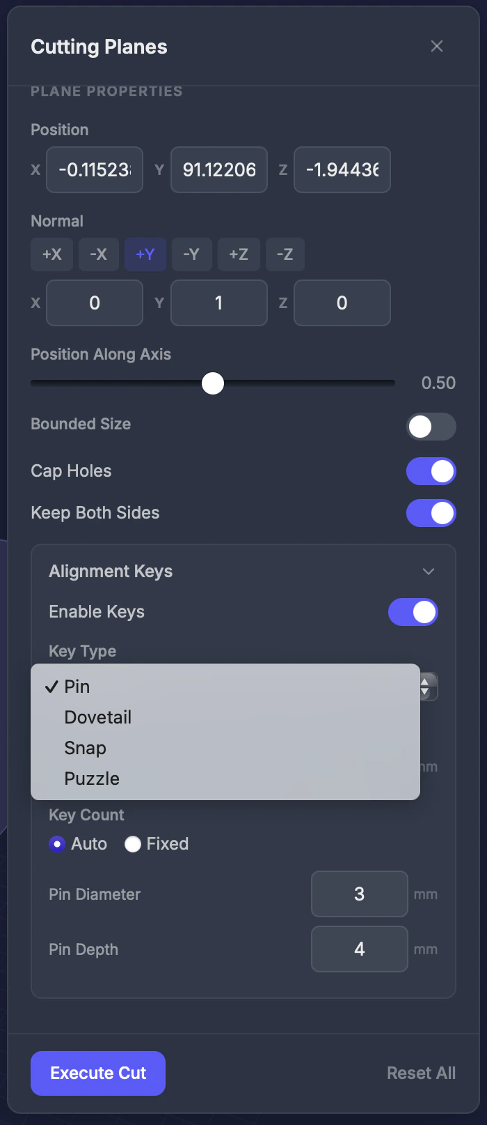
Key types
Key settings
- Enable keys — Toggle to add keys at the cut surface
- Key type — Choose from the four types above
- Clearance — Gap between key and socket (0.05–0.5 mm). Adjust for your printer’s tolerance.
- Count — Auto (placed automatically) or a fixed number
The two pieces
Executing a keyed cut produces one sealed, printable piece per side — each carrying the matching alignment keys so the parts line up cleanly when you assemble them.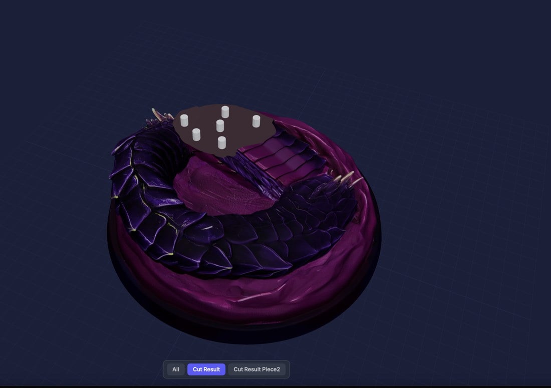
Part 1 — with alignment keys
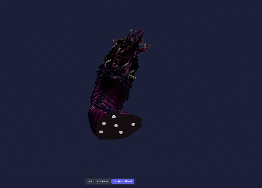
Part 2 — with matching keys
Step by step
1
Select the Cut tool
Click Cut in the Interactive Tools section of the toolbar.
2
Set the cut orientation
Pick a Normal preset (+X, -X, +Y, -Y, +Z, or -Z), or enter a normal vector.
3
Position the cutting plane
Drag the Position Along Axis slider or the plane gizmo in the viewport — you’ll see a preview plane.
4
Enable Keep Both Sides
Toggle on if you want both halves saved.
5
Add keys (optional)
Enable keys and choose a type for assembly-friendly cuts.
6
Execute the cut
Click Execute Cut. Download the pieces from the results.
Tips
- Pin keys are the safest choice if you’re unsure which type to use
- Increase key clearance (0.2–0.3 mm) for FDM printers; use lower clearance (0.05–0.1 mm) for resin printers
- Use the viewport to visually confirm the cut location before executing