

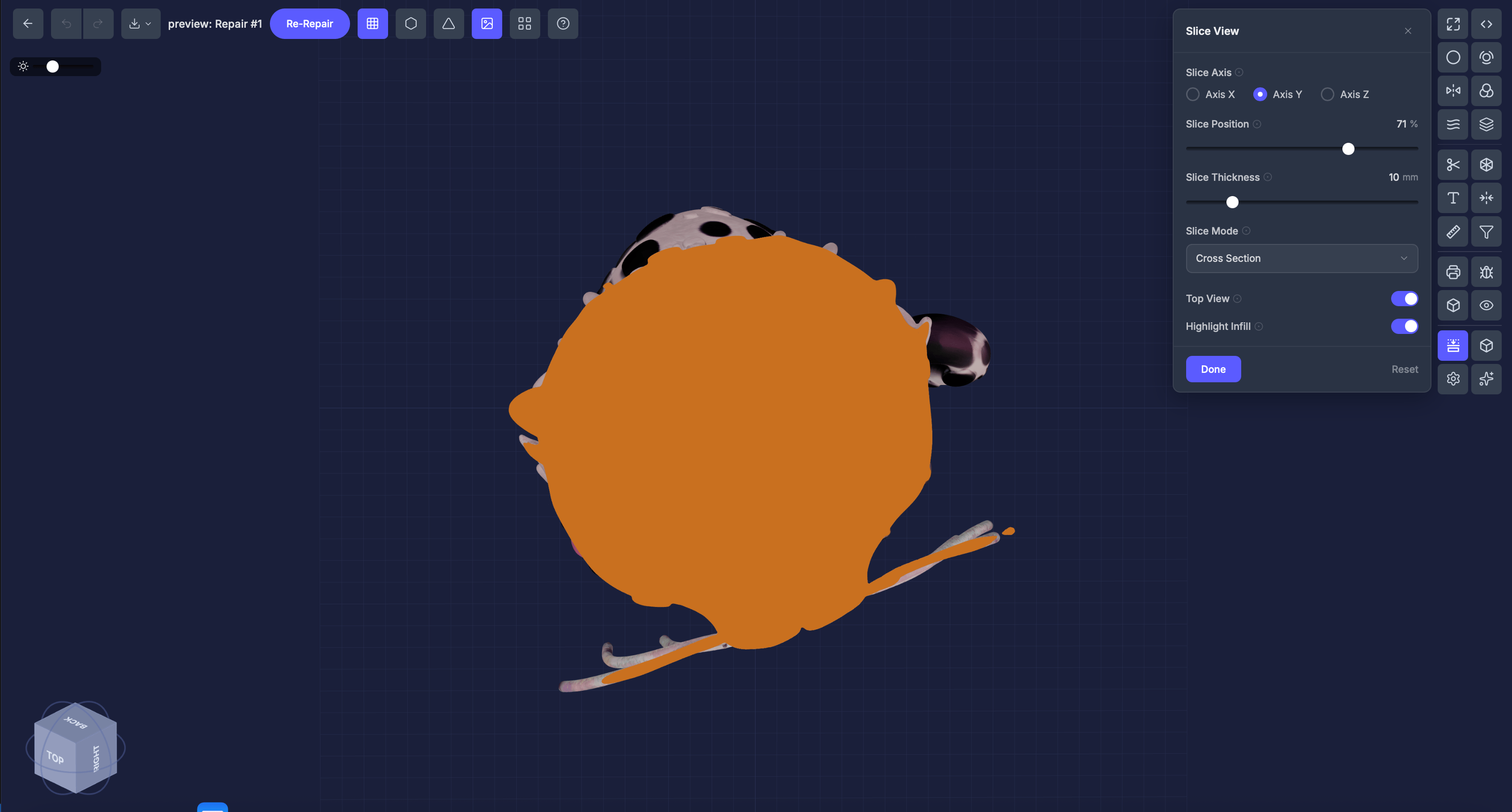
When to use this
- Verify that hollowing created even wall thickness
- Check that lattice infill looks correct inside the model
- Inspect internal geometry for unexpected features
- Visualize how your model will look when sliced for printing
Settings
Slice axis
X, Y, or Z — the direction to slice through.Position
Drag the slider (0–100 percent) to move the slice plane through the model.Slice Thickness (mm)
Thickness of the visible slice. Range 1–50 mm (default 10).Highlight Infill
Toggle (on by default) that caps the cross-section in steel-blue so the cut surface stands out.Step by step
1
Select the Slice tool
Click Slice View in the Inspection Tools section.
2
Choose an axis
Select X, Y, or Z.
3
Drag the slider
Move through the model to inspect different cross-sections.
4
Highlight the infill
Keep Highlight Infill on to cap the cross-section in steel-blue for clearer visualization of the cut boundary.
Tips
- Try all three axes to get a complete picture of the interior
- After applying lattice, slice through to verify the pattern fills the interior evenly
- Use this alongside Object Info to understand your model’s internal structure