> ## Documentation Index
> Fetch the complete documentation index at: https://docs.3dpreppro.com/llms.txt
> Use this file to discover all available pages before exploring further.
# Cut Mesh
> Slice your model into pieces with optional interlocking keys
Cut Mesh slices your model along a flat plane, splitting it into separate pieces. Essential for models too large for your printer, or when you want to print and assemble sections separately.
## When to use this
* Your model is too big to print in one piece
* You want to paint or finish individual parts separately
* You need to print at a higher resolution by splitting into smaller pieces
## Settings
### Normal
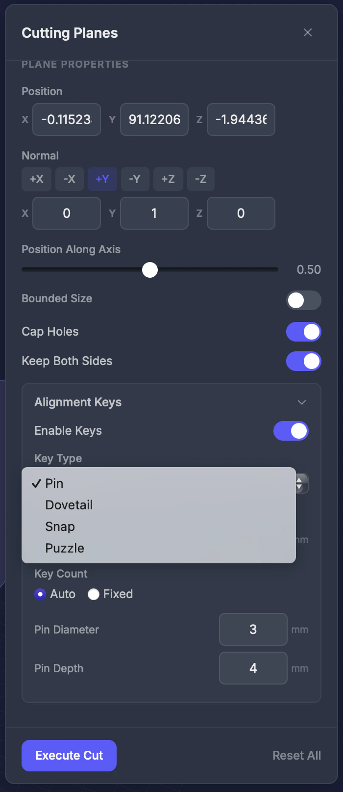
Set the plane's orientation using the **Normal** presets — **+X**, **-X**, **+Y**, **-Y**, **+Z**, or **-Z** — or type an exact direction into the **X / Y / Z** normal fields (values auto-normalize). New planes start with a **+Y** normal.
### Position
Set where the plane sits with the **Position X / Y / Z** fields, or drag the **Position Along Axis** slider (**0.00** to **1.00**) to slide the plane through the model along its normal. You can also drag the plane directly in the viewport using its gizmo. A preview appears in the viewport.
### Cap holes
Toggle (default: on). Fills the cut surface so each piece is sealed and printable.
### Keep both sides
Toggle (default: on). When on, **both** halves are saved as separate pieces.
## Interlocking keys
When **Keep Both Sides** is on, you can add interlocking keys so the pieces snap or fit together after printing.
 ### Key types
| Type | Description | Best for |
| ------------ | ------------------------------- | --------------------------------- |
| **Pin** | Cylindrical peg and hole | Universal, easiest to print |
| **Dovetail** | Trapezoidal cross-section | Strong, self-aligning |
| **Snap** | Mushroom-shaped ball and socket | Clicks into place, no glue needed |
| **Puzzle** | T-shaped interlock | Very secure, hard to pull apart |
### Key settings
* **Enable keys** — Toggle to add keys at the cut surface
* **Key type** — Choose from the four types above
* **Clearance** — Gap between key and socket (0.05–0.5 mm). Adjust for your printer's tolerance.
* **Count** — Auto (placed automatically) or a fixed number
## The two pieces
Executing a keyed cut produces one sealed, printable piece per side — each carrying the matching alignment keys so the parts line up cleanly when you assemble them.
### Key types
| Type | Description | Best for |
| ------------ | ------------------------------- | --------------------------------- |
| **Pin** | Cylindrical peg and hole | Universal, easiest to print |
| **Dovetail** | Trapezoidal cross-section | Strong, self-aligning |
| **Snap** | Mushroom-shaped ball and socket | Clicks into place, no glue needed |
| **Puzzle** | T-shaped interlock | Very secure, hard to pull apart |
### Key settings
* **Enable keys** — Toggle to add keys at the cut surface
* **Key type** — Choose from the four types above
* **Clearance** — Gap between key and socket (0.05–0.5 mm). Adjust for your printer's tolerance.
* **Count** — Auto (placed automatically) or a fixed number
## The two pieces
Executing a keyed cut produces one sealed, printable piece per side — each carrying the matching alignment keys so the parts line up cleanly when you assemble them.
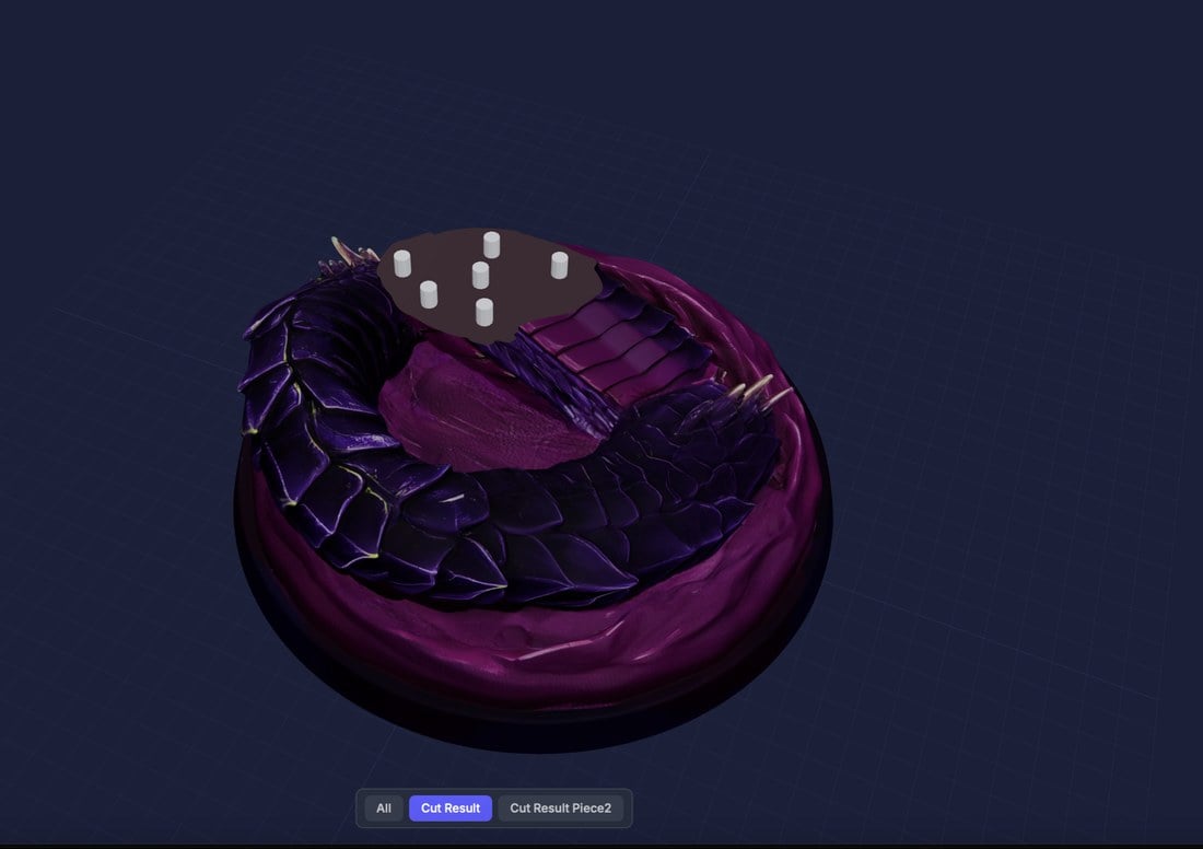
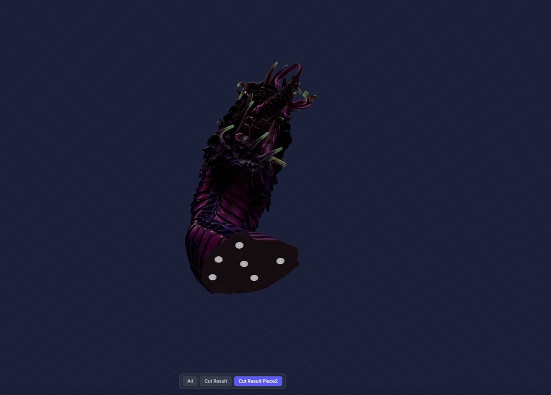 Switch between the results with the **Cut Result** and **Cut Result Piece2** tabs under the viewer, or **All** to see both together.
## Step by step
Click **Cut** in the Interactive Tools section of the toolbar.
Pick a Normal preset (+X, -X, +Y, -Y, +Z, or -Z), or enter a normal vector.
Drag the Position Along Axis slider or the plane gizmo in the viewport — you'll see a preview plane.
Toggle on if you want both halves saved.
Enable keys and choose a type for assembly-friendly cuts.
Click **Execute Cut**. Download the pieces from the results.
## Tips
* **Pin keys** are the safest choice if you're unsure which type to use
* Increase key clearance (**0.2–0.3 mm**) for FDM printers; use lower clearance (**0.05–0.1 mm**) for resin printers
* Use the viewport to visually confirm the cut location before executing
Switch between the results with the **Cut Result** and **Cut Result Piece2** tabs under the viewer, or **All** to see both together.
## Step by step
Click **Cut** in the Interactive Tools section of the toolbar.
Pick a Normal preset (+X, -X, +Y, -Y, +Z, or -Z), or enter a normal vector.
Drag the Position Along Axis slider or the plane gizmo in the viewport — you'll see a preview plane.
Toggle on if you want both halves saved.
Enable keys and choose a type for assembly-friendly cuts.
Click **Execute Cut**. Download the pieces from the results.
## Tips
* **Pin keys** are the safest choice if you're unsure which type to use
* Increase key clearance (**0.2–0.3 mm**) for FDM printers; use lower clearance (**0.05–0.1 mm**) for resin printers
* Use the viewport to visually confirm the cut location before executing